Revolution Board Setup
Introduction
Welcome to the Revolution (Revo) board setup page. Here you will find a number of video tutorials to assist you in setting up your new Revo board.
Along with the tutorials you will also find links to the relevant Wiki pages to assist you in setting up the best Flight Controller board on the market.
WELCOME TO THE OP EXPERIENCE.
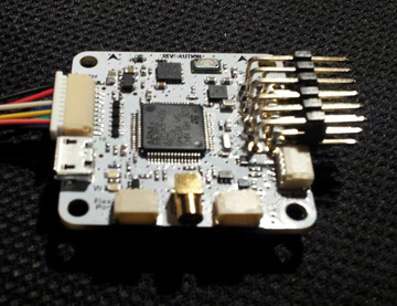
The OpenPilot Revolution board, also called ‘Revo’, is a new breed of Autopilot using the STM32F4 series, 210MIPS ARM Micro-controller. This is important, as it contains a hardware floating point unit (FPU), which is a huge advancement for hobby-class autopilots. Of course, OpenPilot has been 32bit since day one, and the FPU is another step up the performance ladder. The FPU allows precise, low-latency processing of real-life measurements using advanced attitude estimation algorithms.
The Revolution is a flight control computer with autopilot, intended for multirotors, helicopters and fixed wings. It is a full 10DOF with gyroscope, accelerometer, magnetometer and pressure sensors.
Setting up your Revolution Board for the first time
You have just received a brand new Revolution board and are itching to mount it in your air frame, follow the Video Tutorial below.
Vehicle Setup Wizard
Once you have mounted your Revo on your frame you need to configure it through the Ground Control Station (GCS) using the Vehicle Setup Wizard, follow the Video Tutorial below for setting up on a Multirotor.
Sensor calibration
Tuning your Revolution

Technical description
CPU
CPU is the STM32F405RGT6 chip, with ARM Cortex-M4 core at 210MIPS, FPU, and saturation arithmetics DSP functions.
The chip features a range of built-in hardware modules that can bo programmed once and function independentely, requiring little to no CPU overhead. These include 14x multichanel timers, 3x synchronous-sampling ADC serving up to 24 channels, 2x DAC, matrix memory controller with 16-stream DMA, and other. Communication modules include USB2.0, 3x I2C, 3x SPI, 4x USART, 2x CAN and SIDO. All these modules can be configured for accessing the chip pins using a flexible switch matrix, or disabled to save power.
It even contains a real time hardware calendar if you want a wake up flight.
The software and settings are loaded through USB connector and no-hassle update function in the GCS (Ground Control Station).
Modem
The board features built-in 433MHz OPLink Modem.
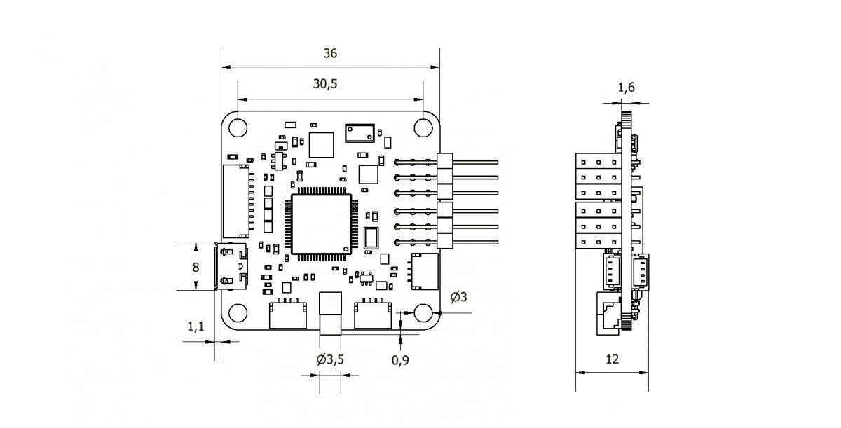
Dimensions
OpenPilot products use the standard OpenPilot footprint, and hence has the same dimensions and mounting holes as the OpenPilot Revo, GPS, OSD and PipX boards.
(All dimensions are in millimeters.)
Ports
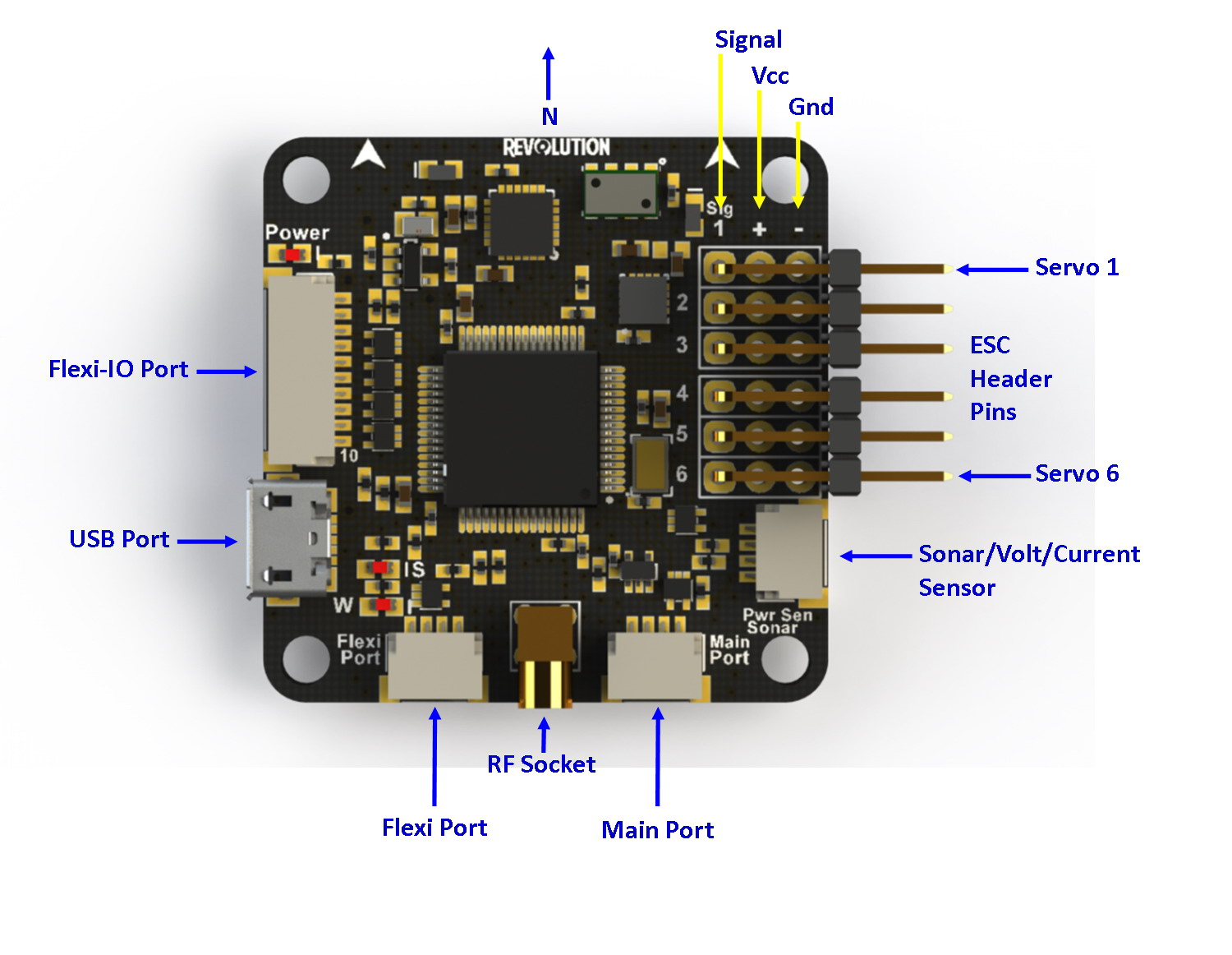
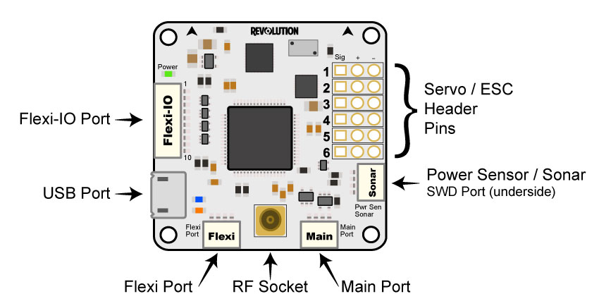
Servo 1-6: These are the PWM outputs that go to servos or ESCs. Power is typically applied through these headers from only one of the ESCs. The positive (Vcc) and negative (Gnd) pins are indicated on this diagram and the board.
- Servo output pin layout is:
- Outside –> ground
- Middle –> 5V - 8.4V
- Inside –> signal
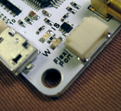
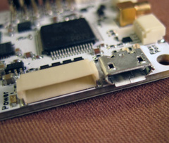
Flexi-IO Port: JST-SH 10-pin. The receiver port can act as an input or output port depending on the configuration which is set in the Hardware Settings. Configuring the receiver port as an output port allows the user to assign more output channels then the 6 standard servo outputs.
PWM -vs- PPM Recievers
Please be aware that not all receivers can be configured to use a PPM output. It is the user’s responsibility to research this feature in regards to the desired receiver they wish to use for PPM and ensure it can be used as such. Many hours of frustration can occur while trying to troubleshoot why you can’t get your radio to connect to the board with PPM if using a receiver than isn’t designed with that feature! Simply make sure the receiver can do it before trying to set it up that way.
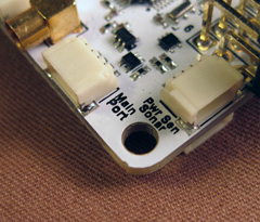
MainPort: JST-SH 4-pin. This is a serial USART whose baud rate can be adjusted through the GCS. Optionally, Futaba S.Bus receiver, Spektrum/JR satellite receiver or GPS can be mapped to the MainPort. Default configuration is Telemetry for connecting an RF modem.
FlexiPort: JST-SH 4-pin. The function of this port also depends on the configuration and can be configured for I2C or Serial. The default configuration doesn’t use this port, but it can be used for Telemetry, GPS, Spektrum satellite receivers (all working), and other I2C peripherals (under development).
RF Socket: Antenna connection socket for on-board OPLink Modem.
Pwr Sen/Sonar Port: JST-SH 4-pin. This port can be configured to accommodate an Autopilot current sensor and a low cost Sonar sensor such as the HC-SR04. It can also be used as a general purpose input/output port or as a one or two channel analog input port.
Note
Please note that the output rate on the output channels from the ReceiverPort cannot be set individually. If servos are connected to this outputs, you must ensure that they can work with the defined output rate for choose a high output rate to support an octocopter configuration, the update rate from the output channels from the ReceiverPort are bound to the update rate from channels 5 & 6. In this case, you cannot connect analog servo’s to these outputs since an analog servo only supports an output rate of 50Hz.
Sensor suite
- 3 Axis Gyro
- 3 Axis Accelerometer
- 3 Axis Magnetometer
- Barometric pressure sensor
MPU
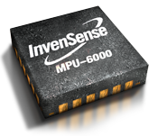
The MPU-6000 combines a 3-axis gyroscope and a 3-axis accelerometer on the same silicon die. This sensor can also be found on the CC3D and already has a proven track record of great flight performance.
Pressure Sensor/Altimeter
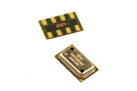
When it came time to select a barometric pressure sensor, there were many to choose from and many were not up to the task. For the Revolution, OpenPilot selected the Measurement Specialties MS5611.
The MS5611 is not just any barometric pressure sensor, it is purpose-built, and has a very high resolution. As a result, it is ideal for use as a UAV altitude sensor. The sensor is so sensitive that it can sense a vertical shift of only 10 cm. The Revolution uses the newer MS5611-01BA03 version of this sensor that is far less susceptible to light interference than the older, plastic case versions.
Magnetometer
Whether you are in ‘Position Hold’ while taking aerial photographs, or you are flying a fixed-wing UAV on a pre-planned flight path, it’s vitally important to have accurate heading information. The Honeywell HMC5883L is a three-axis digital compass module which provides rapid updates to changes in orientation which are accurate to a tolerance of 1° to 2°.
Connectivity
Just like CC & CC3D, the Revo has many ports, but a key new addition is the Flexi-IO Port. A lot of thought went into creating a small device that’s flexible for use with multirotor platforms, helicopters and fixed wing aircraft, as well as making connectivity as future proof as possible.
Flexi-IO
The Flexi-IO port uses a 10 pin JST-connector and is designed to perform several different functions. The port is used for control input and output and can be configured to serve 6 PWM inputs or outputs. A mixture of other modes can also be configured.
- 6 channel PWM input for receiver + 2 GPIO
- 1 channel PPM input for receiver + 5 PWM I/O channels for motor/servo or sensors
- 4 pin SPI + 1 UART + 2 PWM I/O (PPM mode)
- CAN with external transceiver, UART, 4 PWM I/O / PPM
The full unshared SPI I/O port can be used as master or slave, allowing you to interface the Revolution board to any other embedded system like, for example, the Overo Linux boards. This also allows use of the Revo for advanced robotic applications.
An additional board can provide raw CPU power and high level functions, ranging from networking and data storage, up to video analysis, autonomous behaviour and artificial intelligence. The Revolution board will act as a reliable real time hardware controller and sensor platform, keeping your autonomous vehicle safely under control at all times.
Pinout
| Pin | Color | PWM Function | PPM Function | PPM+Telemetry Function | PPM+Outputs Function | Outputs Function | Telemetry Function |
|---|---|---|---|---|---|---|---|
| 1 | Black | Ground | Ground | Ground | Ground | Ground | Ground |
| 2 | Red | Vcc | Vcc | Vcc | Vcc | Vcc | Vcc |
| 3 | |||||||
| 4 | |||||||
| 5 | White | PWM Input 1 | PPM Input 1-8 | PPM Input 1-8 | PPM Input | PWM Output 12 | |
| 6 | Blue | PWM Input 2 | PWM Output 7 | PWM Output 7 | |||
| 7 | Yellow | PWM Input 3 | Telemetry TX | PWM Output 8 | PWM Output 8 | Telemetry TX | |
| 8 | Green | PWM Input 4 | Telemetry RX | PWM Output 9 | PWM Output 9 | Telemetry RX | |
| 9 | Orange | PWM Input 5 | PWM Output 10 | PWM Output 10 | |||
| 10 | Violet | PWM Input 6 | PWM Output 11 | PWM Output 11 |
FlexiPort

The Revo uses the same FlexiPort as the CC3D. The port can be used as either a UART or for I2C bus connectivity. It can be connected to serial devices like the OP GPS or any I2C device like the the EagleTree Airspeed expander module, ADCs, I2C ESCs and a lot more. It can also be used to connect Spektrum DSM2/DSMX Satellite to be used as receiver, or any other custom component interfacing with I2C or a serial connection including custom extension boards. Of course, it’s also possible to run a serial Telemetry link to the GCS over the FlexiPort.
Pinout
| Color | JST-SH Pin | Voltage | Serial Function (GPS, Telemetry) | I2C Function | DSM |
|---|---|---|---|---|---|
| Black | 1 | GND | GND | GND | GND |
| Red | 2 | 4.8V - 15V | PWR Out (VCC Unregulated) | PWR Out (VCC Unregulated) | PWR Out (VCC Unregulated) |
| Blue | 3 | 3.3V | TX | SCL | |
| Orange | 4 | 3.3V (5V Tolerant) | RX | SDA | TX (Signal) |
Warning
The Spektrum adapter should only be powered by 3.3V, a step down adapter must be used.
Warning
The PWR Out voltage is dependent on the CC supplied voltage. Verify that you use the correct voltage for your S.BUS receiver.
MainPort
Standard serial port/S.Bus port (same as CC3D). This can be used to connect serial devices like Telemetry, OP GPS, Futaba S.Bus receivers or Spektrum DSM2/DSMX satellites (to be used as a receiver), freeing in these cases the Flexi-IO port for other uses. These systems use a single wire to help cut down cable clutter.
Pinout
| Color | JST-SH Pin | Voltage | Serial Function (GPS, Telemetry) | DSM | S.BUS |
|---|---|---|---|---|---|
| Black | 1 | GND | GND | GND | GND |
| Red | 2 | 4.8V - 15V | PWR Out (VCC Unregulated) | PWR Out (VCC Unregulated) | PWR Out (VCC Unregulated) |
| Blue | 3 | 3.3V | TX | ||
| Orange | 4 | 3.3V (5V Tolerant) | RX | TX (Signal) | TX (Signal) |
Current / Sonar
This port can be configured to accommodate an Autopilot current sensor and a low cost Sonar sensor such as the HC-SR04. It can also be used as a general purpose input/output port or as a one or two channel analog input port.
Pinout
| Color | JST-SH Pin | Voltage | Power Sensor |
|---|---|---|---|
| Black | 1 | GND | GND |
| Red | 2 | 4.8V - 15V | PWR Out (VCC Unregulated) |
| Blue | 3 | 3.3V | Current Input |
| Orange | 4 | 3.3V (5V Tolerant) | Voltage Input |
See also: Revo - Current/Voltage Sensor Setup
PWM output headers
Just like the CC & CC3D, the Revo has a bank of 6 PWM output headers. If more PWM outputs are needed - the Flexi-IO port can be configured to support up to an additional 6 PWM channels if so required. PWM port 5 can also be configured to communicate with an external analog airspeed sensor or a governor for helicopters.
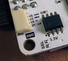
SWD Port
Serial wire debug port. This allows the use of cheap boards like the STM F4 Discovery as an in-circuit debugger to ease the firmware development.
Pinout
| Color | JST-SH Pin | Pin Description |
|---|---|---|
| Black | 1 | GND |
| Red | 2 | NRS |
| Blue | 3 | IO |
| Orange | 4 | CLK |
Micro USB
We have decided to move away from using the mini USB port found on the existing CC and CC3D and instead use a Micro USB port. The Micro USB port has several benefits: it’s physically smaller, more robust, a much more widely adopted standard, and is the same type of port found on the majority of mobile phones. In all likelihood, you’ll already have one of these cables at home.
The USB port provides a USB composite device with the following functions:
- OpenPilot HID device (default GCS interface, uses PC system drivers)
- CDC virtual serial port (telemetry, debugging, serial bridge mode relaying data from/to physical serial port to the virtual one for GPS/Bluetooth module setup, etc)
- 8-channel HID joystick (passes data from all supported R/C inputs to PC flight simulators)
And all these at the same time.
OPLink Modem
The Revolution has its own OPLink Mini built right onto the board! This is not only a 10DoF flight controller with an ST32F4 processor in the same small footprint as the CC3D, but also has its own LRS modem. The modem is directly powered from the Revolution itself, so you don’t need to worry about any additional power supply.
Of course, the on-board modem will have the same functionality as the OPLink Mini. Both are fully configurable from the GCS.
Operating on the 433MHz band (a 900Mhz version will be released at a later date), the modem provides a direct telemetry link between the GCS and your flight controller. And just as with the OPLink Mini, you can adjust the output RF power for compliance with any governmental RF regulations, or it can be disabled entirely.
DIY Board
Schematics, PCB Layout, Gerbers, BOM:
Revolution.zip